The risers are designed to meet the following design requirements:
• Vortex Induced Vibration
• Equivalent Stress
The methods of the analyses are described in the following subsections.
Vortex Induced Vibration
The allowable span lengths for the vortex induced vibration criteria are calculated based on riser general arrangement drawings and DNV 1981, whereby the reduced velocity is defined as:
Another parameter controlling the dynamic vibration is the stability parameter (KS) defined as:
Based on the calculated stability parameter, the limiting reduced velocity can be obtained from Figure A.3 of DNV 1981. As per DNV 1981, the in-line oscillation of a free span are initiated at lower velocities than those required for the onset of cross flow motion. Therefore, the maximum allowable span length for the in-line motion criterion will automatically satisfy the cross-flow criterion. The equation for reduced velocity (Vr) can be re-arranged as follows:
Combining the two equations and solving for L:
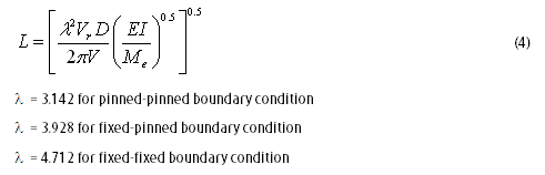
The vortex shedding analysis is performed using in-house spreadsheet files. The spreadsheet calculates the allowable riser span length to avoid the onset of pipeline in-line and cross flow oscillations induced by vortex induced vibration, which complies with the DNV 1981 method. Based on the calculated span length, the riser clamp elevation is then identified such that the clamp elevation spacing is always lower than the riser maximum span length.
Steady current and wave velocity are considered in the riser vortex vibration analysis
Riser analysis have been analyzed using AUTOPIPE software
Wednesday, November 17, 2010
Friday, November 12, 2010
ORIGINATOR IS BACK
OGA PIPELINE is back!!!!
It's been a long time I didn't write someting in my blog. I'm so sorry to all followers who waiting info about oil and gas pipeline in this blog. To be honest, the year 2010 was a busy and challenge year for me due to handle a big project and also involved in project management.
Normally, few years after you involved in specializing work, you've been forced to jump into management. But, this is depends on work load, either you fully or partially involved. Samething happened to me, which is previously one of my project required additional pipeline design, and I has been selected to be a focal person (Contractor Representative) between design consultant and Contractor(TLO).
The job title still considered as a part of management, but the work scope was small which is Revisit Pipeline Detailed Design (Pipeline Route Analysis, Pipeline Bottom Roughness Analysis, Expansion Analysis, On Bottom Stability Analysis and drawings).
Doing a management work is not easy as what we expect. I've produce ITB (Invitation to Bid Doc), check the progress report and design report (almost every week), find an info for consultant to to do their job, and manage to complete the job at the agreed date. Management work is something that you play with the time. Same like the time you come to the office, for sure you're not coming after 9am everyday right?.
But, to be honest, I'm still love my job as a Pipeline Engineer, because I love to do calculation and realized I'm specialist. Other than that, currently I'm in progress to pursue my dream, to get the Ir status (Professional Engineer). Part of the requirement are to attend a course, produce experiences report, and interview.
Back to our main topic, after this I'm promised to spent sometimes to update my blog. And I'll start finish the Pipeline Design first before I bring all of you to the other field which is Pipeline Installation.
It's been a long time I didn't write someting in my blog. I'm so sorry to all followers who waiting info about oil and gas pipeline in this blog. To be honest, the year 2010 was a busy and challenge year for me due to handle a big project and also involved in project management.
Normally, few years after you involved in specializing work, you've been forced to jump into management. But, this is depends on work load, either you fully or partially involved. Samething happened to me, which is previously one of my project required additional pipeline design, and I has been selected to be a focal person (Contractor Representative) between design consultant and Contractor(TLO).
The job title still considered as a part of management, but the work scope was small which is Revisit Pipeline Detailed Design (Pipeline Route Analysis, Pipeline Bottom Roughness Analysis, Expansion Analysis, On Bottom Stability Analysis and drawings).
Doing a management work is not easy as what we expect. I've produce ITB (Invitation to Bid Doc), check the progress report and design report (almost every week), find an info for consultant to to do their job, and manage to complete the job at the agreed date. Management work is something that you play with the time. Same like the time you come to the office, for sure you're not coming after 9am everyday right?.
But, to be honest, I'm still love my job as a Pipeline Engineer, because I love to do calculation and realized I'm specialist. Other than that, currently I'm in progress to pursue my dream, to get the Ir status (Professional Engineer). Part of the requirement are to attend a course, produce experiences report, and interview.
Back to our main topic, after this I'm promised to spent sometimes to update my blog. And I'll start finish the Pipeline Design first before I bring all of you to the other field which is Pipeline Installation.
Monday, May 31, 2010
PIPELINE EXPANSION ANALYSIS
Pipeline expansion analyses are calculated using the strain balance method.
The load such as internal pressure, temperature, friction and some effect on residual lay tension will cause to expand at its free end with includes the stresses and force in the pipe wall.
Analysis Methodology
The axial force (Pr) acting on the pipeline is taken as:-
At a distance x, from the pipeline free end (platform end), the soil frictional force (Pfsoil) preventing this movement is represented by the following equations:-
The pipeline end movement occurs up to a point when the expansion force is equivalent to the soil frictional force. This point is called the virtual anchor point. The x value can be solved to obtain virtual anchor point Lexpand1 (hot end) and Lexpand2 (cold end) from the following equations:-
Tuesday, March 9, 2010
Sunday, February 7, 2010
Wednesday, December 16, 2009
SapuraAcergy wins Devil Creek development project pipeline contract (Ref : http://www.offshore-mag.com)
Published: Oct 2, 2009
Offshore staff
LONDON -- Apache Energy has awarded SapuraAcergy a $170-million contract for the Devil Creek development project (DCDP) offshore Australia.
SapuraAcergy’s scope of work involves the transportation and installation of 91 km (57 mi) of 16-in. (41-cm) rigid pipeline including a shallow water beach approach, subsea tie-in, and stabilization works together with a wellhead platform of a 1,700-metric ton (1,874 ton) four leg jacket and a 450-metric ton (496-ton) topside processing module.
Engineering and project preparations will begin immediately in Kuala Lumpur and Perth. Offshore installation is scheduled to begin in late 2010 using the positioning heavy lift and pipelay vessel Sapura 3000 and third-party support vessels.
10/02/2009
PIPELINE SPANNING ANALYSIS
Introduction
Assessment of pipeline where determining the acceptability of pipeline freespan without effected the structural integrity, which was measure the allowable span of pipeline with respect to certain criteria as per below:
-Static stress cross flow vortex shedding for the maximum design wave data combined with steady current.
-In-line vortex shedding using steady current only (no wave induce current)
A lot of factor that contribute the pipeline span like
-Uneven seabed
-Pipeline crossing
-Coral
Static Spanning
To maintain the consistency with other features in pipeline, span length based on static stress considerations are governed by:
-Selfweight and coatings
-Environmental factor
-Operational Factor
-Hydrotest Factor
All method of pipeline spanning analysis is according to DnV 81 as follow:
Dynamic span is to check the allowable span for installation, hydrotest and operation under the steady state current conditions.
Analysis is according to DnV 81 which fluid flow passing a free span that cause unsteady flow patterns due to vortex shedding, which may lead to oscillations of the pipe. vortex shedding frequency may coincide with, or be a multiple of, the natural frequency of the pipe. Harmonic or sub-harmonic excitation of the free span may then result.
SYMETRIC VORTEX SHEDDING
WEAK ALTERNATE VORTEX SHEDDING
STRONG ALTERNATE VORTEX SHEDDING
Saturday, December 12, 2009
Swiber to lay Myanmar gas lines (Ref : http://www.offshore-mag.com)
Published: Nov 25, 2009
Offshore staff
SINGAPORE -- Swiber Holdings has won its first pipeline installation contract offshore Myanmar. An unnamed oil and gas company has issued a Letter of Award valued at $77 million for laying of 150 km (93 mi) of subsea gas pipelines.
Preparation for the project should get under way next month, with the installation program due to be completed in 2Q 2010.
Swiber is expanding its vessel pool, in anticipation of increased demand for offshore construction work. The fleet currently comprises 34 offshore vessels and 10 construction vessels, and Swiber expects to own and operate a total of 52 vessels by 2011.
11/25/2009
Monday, November 23, 2009
Monday, November 16, 2009
CATHODIC PROTECTION DESIGN
-External Corrosion Coating is a combination of both coating and anode.
ANODE
-In the event of coating damage or deterioration, a secondary anode system is also provided, typically in the form of zinc or aluminum alloy sacrificial bracelet anodes.
-Cathodic Protect design is based on DNV-RP-F103.
-The minimum required anode length corresponding to the selected anode bracelet thickness to meet both minimum weight and surface area requirement which is the thickness of anode must to be same as thickness of concrete coating
-Cathodic Protection design calculation as per below :
EXTERNAL CORROSION COATING
-List of external corrosion coatings and the maximum temperature limit as per below:
ANODE
-In the event of coating damage or deterioration, a secondary anode system is also provided, typically in the form of zinc or aluminum alloy sacrificial bracelet anodes.
-Cathodic Protect design is based on DNV-RP-F103.
-The minimum required anode length corresponding to the selected anode bracelet thickness to meet both minimum weight and surface area requirement which is the thickness of anode must to be same as thickness of concrete coating
-Cathodic Protection design calculation as per below :
EXTERNAL CORROSION COATING
-List of external corrosion coatings and the maximum temperature limit as per below:
Monday, October 26, 2009
NEW OGA PIPELINE LOGO
After a years started, OGA PIPELINE officially launch a new logo. Start from today, any other bussiness that involve by OGA PIPELINE will using these logo. Thanks for all your support and stay tuned for more info in OGA PIPELINE.
From now on, OGA PIPELINE has been registered as:
OGA PIPELINE ENTERPRISE
(Reg. No. : 001903538-H)
No. 401 Block A-12, Section 1 Wangsa Maju,
Setapak,
53300 Kuala Lumpur
Tuesday, October 20, 2009
PIPELINE ENGINEERING SCOPE OF WORK
Sunday, October 11, 2009
OGA PIPELINE LAUNCH JOBSEEKERS AND COMPANY POST PACKAGE
PLEASE REFER TO TABLES BELOW FOR FURTHER INFO :


SEQUENCE OF PAYMENT METHOD :
1. CHOOSE THE PACKAGE AND CODE NO.
2. BANK IN THE AMOUNT ACCORDING TO THE CODE NO. TO PUBLIC BANK (ASRI BIN RAFIE, A/C. NO. : 4875843906) VIA DEPOSIT MACHINE OR ONLINE BANKING.
3. ONCE PAYMENT DONE, PLEASE KEEP THE RECEIPT AS PROOF OF PAYMENT AND SEND SMS AND EMAIL WITH BELOW DETAILS TO OGA PIPELINE (012-mailto:012-6474886/asri.rafie@gmail.com) FOR VERIFICATION:-
- NAME
- PACKAGE CODE NO.
- BANK IN AMOUNT
- BANK IN DATE
- BANK IN TIME
4. PACKAGE SERVICES WILL START ONCE YOU RECEIVED THE VERIFICATION EMAIL AND SMS FROM OGA PIPELINE. THANK YOU
5. OR YOU CAN MAKE A PAYMENT VIA CREDIT CARD/DEBIT CARD : SEE AT SIDE PAGE- (PACKAGE A-JOBSEEKERS AND PACKAGE B-COMPANY SEARCH). SEE THIS LOGO
Wednesday, September 9, 2009
Part 11 - Field Engineer vs Pipeline Engineer
Roles and Responsibilities Of Field Engineer
-Be conversant with the technical and commercial aspects of the projects and to have a full understanding of the scope of work, as provided be the Project Manager/Vessel Superintendent.-To prepare offshore operations procedures at the requested by Project Manager.
-To prepare task plans during offshore operation based on the installation procedures.
-To become familiar with all the vessel operation/limitations, in order to improve design, operational schedule, procedures and safety.-Participate in daily project meetings and toolbox talks.
-Liase with coordinate the activities of vendors and subcontractors as and when required as part of the Project, without commercial authority.
-Implement and organise any approved modifications to the Project, ensuring all changes are fully documentedand included in the appropriate documents.
Roles and Responsibilities Of Pipeline Engineer
-Review Client's technical documentation and requirements.
-Prepare the design and basis/CTRs for the pipeline design and interface with the relative process and structures and installation.
-Check the result of surveys carried out by sub-contractors and optimise the laying route.
-Assist with the selection of spread/methods and perform/review installation design analysis for the pipeline system.
-Assist the pipeline lead or the project engineering manager for solving technical problems arising during project development and the interfacing/supporting the procurement department.
-Perform/verify all discipline analyses and calculation notes required to design the pipelines system, including the engineering activities of third parties/sub contractors.
-Define Standards and procedures for the relative engineering area and contribute to software evaluations.
-Solve all the engineering problems arisen from day to day installation works.
-To ensure safe and efficient offshore installation operations.
-To find the optimum and the best rectification design of any repair.
-Engineering analysis scope of work details :
Pipelay analyses using pipelay barge.
Riser installation & davit lifts analyses.
Pipeline Spanning calculations
Stinger ballast calculations check.
Pipeline sidewalking analyses.
Abandonment & recovery analyses.
Pipeline bowstring & anchor start-up
Mid point tie-in analyses.
Thursday, August 20, 2009
Continue of Part 9 - On Bottom Stability Analysis

On Bottom Stability Using AGA
Level 1
-Its calculate the static stability
-Airy waves theory and Morison force apply
- A cohesive soil retains its restraining force
Level 2
-Calculates value of design wave height spectral density function
-The peak frequency of the bottom velocity spectrum is determined
-Maximum and minimum in-line hydrodynamic forces for the largest 200 waves contained in an assumed 4-hours long build-up sea state are calculated.
-Maximum and minimum in-line forces for the largest 50 waves during a subsequent 3hours long design sea stated are as in step above.
-Hydrodynamic forces for a complete cycle are calculated for four level of bottom velocity which are expected in a 3hours long design sea state.
-The four bottom velocities are :
- U1/3 = 1.0Us
- U1/10 = 1.27Us
- U1/100 = 1.66Us
- U1/1000 = 1.86Us
Output example from my project before :

Friday, August 7, 2009
Part 10 - Offshore Trip For 28in KUMANG Pipeline
I've been given a task by Enterprise 3 OCS for going to offshore KUMANG monitorized 28in KAKG-A to MLNG-2 pipeline lay & recovery @50m WD. It's a good experience step where I've been exposed for laying a bigger and heavier pipeline.
At the first day on board, I am setup the stinger rollers and collected some information about the rollers condition for reporting purposes to office. The next day, Enterprise 3 is towing from kp 186 nearshore to KP104 at offshore for recovery the 28in pipeline and the journey takes 10hours. Once the barge ready at the location, anchors have been deploy with respect to the pattern done by field engineer.
For this job, pipeline analysis is done by me, and as per OFFPIPE shows the marginal stresses which is almost to allowable stresses, where further details are monitorized to aviod from pipeline buckle. But, everything just follow the plan and 28in pipeline is recovered during day shift.
HOT NEWS - MALAYSIA OIL & GAS

Seven in running for Petronas tender
By Tan Hwee Hwee
By Tan Hwee Hwee
Seven contractors are said to be running for the five transportation and installation packages offered under the Petronas’ umbrella tender issued on behalf of 11 PSC operators in Malaysia. The contenders include the five mentioned in an earlier report : SapuraCrest’s affiliate, TL Offshore, Bumi Armada-J Ray McDermott, Saipem, Sigurros and PBJV, as well as Global Industries and private Malaysian outfit, Master Offshore.
TL Offshore and the partnership between Bumi Armada and J Ray McDermott, are likely to go for all five packages. Saipem, Global Industries and the three other Malaysian contractors are said to be eyeing at most three of the offered packages, according to industry sources. Of the three smaller Malaysian contractors, PBJV is expected to go on a lone bid for the pipelay packages. Sigurros is said to be seeking a partnership with Sime Darby, while Master Offshore may be looking at recruiting more third party vessels for the bid round.
The final contract or contracts to be awarded will run for a minimum of three years from the second quarter of next year and includes two options each for one year extension. The work scope for 2010 and 2011 has been released and will be executed over a minimum of 84 days and up to 229 days each year. The remaining work for the next three years from 2011 through 2013 will be firmed up during or after the third quarter of 2011.
Work will be carried out using a full marine spread including derrick and/or pipelayers, diving support vessels and anchor handling tug supply vessels. Bids are due for submission in July and the contract could be awarded as early as this November. Industry observers said the firm three-year contract could be worth 3 billion ringgit ($850 million).
Friday, 10 July, 2009, 08:18 GMT last updated: Friday, 10 July, 2009, 08:45 GMT
TL Offshore and the partnership between Bumi Armada and J Ray McDermott, are likely to go for all five packages. Saipem, Global Industries and the three other Malaysian contractors are said to be eyeing at most three of the offered packages, according to industry sources. Of the three smaller Malaysian contractors, PBJV is expected to go on a lone bid for the pipelay packages. Sigurros is said to be seeking a partnership with Sime Darby, while Master Offshore may be looking at recruiting more third party vessels for the bid round.
The final contract or contracts to be awarded will run for a minimum of three years from the second quarter of next year and includes two options each for one year extension. The work scope for 2010 and 2011 has been released and will be executed over a minimum of 84 days and up to 229 days each year. The remaining work for the next three years from 2011 through 2013 will be firmed up during or after the third quarter of 2011.
Work will be carried out using a full marine spread including derrick and/or pipelayers, diving support vessels and anchor handling tug supply vessels. Bids are due for submission in July and the contract could be awarded as early as this November. Industry observers said the firm three-year contract could be worth 3 billion ringgit ($850 million).
Friday, 10 July, 2009, 08:18 GMT last updated: Friday, 10 July, 2009, 08:45 GMT
Tuesday, July 21, 2009
Part 9 - Pipeline On Bottom Stability Analysis

Pipeline on bottom stability is an interaction of pipe, water and soil. The important factor that taken into account is the water flow whereby determining the magnitude and time variation of hydrodynamic drag and lift forces.
The second factor is soil. There have 3 friction will happened which are static, sliding and cohesive friction. So, it’s very important to understand the soil condition at the pipeline route area so that accuracy of analysis achieved.
These are some input provided for on bottom stability analysis :
1. Pipeline Data
Outside diameter
Wall thickness
Density of Pipe
Corrosion Coating Thickness
Corrosion Coating Density
Concrete Coating Thickness
Concrete Coating Density
Field Joint Material Density
Concrete Coating Cutback
Corrosion Coating Cutback
Pipe Joint Length
The second factor is soil. There have 3 friction will happened which are static, sliding and cohesive friction. So, it’s very important to understand the soil condition at the pipeline route area so that accuracy of analysis achieved.
These are some input provided for on bottom stability analysis :
1. Pipeline Data
Outside diameter

Wall thickness
Density of Pipe
Corrosion Coating Thickness
Corrosion Coating Density
Concrete Coating Thickness
Concrete Coating Density
Field Joint Material Density
Concrete Coating Cutback
Corrosion Coating Cutback
Pipe Joint Length
2. Wave and Current Data

Significant Wave Height (Hs)
Spectral Peak Period (Tp)
Wave Angle
Wave Spectrum Type
Water Depth
Current Velocity
Current References Height from Bottom
Peakedness Parameter
3. Physical Parameter
Density of Content
Density of Seawater
Marine Growth Thickness
Soil Type
Mean Grain Size – DNV RP E305
Roughness – DNV RP E305
Undrained Shear Strength (Su) – DNV RP E305
Lift Coefficient – –DNV RP E305
Drag Coefficient – DNV RP E305
Inertial Coefficient – DNV RP E305
Follow Part 9 for continuing of On Bottom Stability using AGA method
Subscribe to:
Posts (Atom)


