The risers are designed to meet the following design requirements:
• Vortex Induced Vibration
• Equivalent Stress
The methods of the analyses are described in the following subsections.
Vortex Induced Vibration
The allowable span lengths for the vortex induced vibration criteria are calculated based on riser general arrangement drawings and DNV 1981, whereby the reduced velocity is defined as:
Another parameter controlling the dynamic vibration is the stability parameter (KS) defined as:
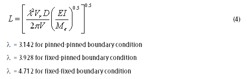
Based on the calculated stability parameter, the limiting reduced velocity can be obtained from Figure A.3 of DNV 1981. As per DNV 1981, the in-line oscillation of a free span are initiated at lower velocities than those required for the onset of cross flow motion. Therefore, the maximum allowable span length for the in-line motion criterion will automatically satisfy the cross-flow criterion. The equation for reduced velocity (Vr) can be re-arranged as follows:
Combining the two equations and solving for L:
The vortex shedding analysis is performed using in-house spreadsheet files. The spreadsheet calculates the allowable riser span length to avoid the onset of pipeline in-line and cross flow oscillations induced by vortex induced vibration, which complies with the DNV 1981 method. Based on the calculated span length, the riser clamp elevation is then identified such that the clamp elevation spacing is always lower than the riser maximum span length.
Steady current and wave velocity are considered in the riser vortex vibration analysis
Riser analysis have been analyzed using AUTOPIPE software
Showing posts with label PIPELINE DESIGN. Show all posts
Wednesday, November 17, 2010
Monday, May 31, 2010
PIPELINE EXPANSION ANALYSIS
Pipeline expansion analyses are calculated using the strain balance method.
The load such as internal pressure, temperature, friction and some effect on residual lay tension will cause to expand at its free end with includes the stresses and force in the pipe wall.
Analysis Methodology
The axial force (Pr) acting on the pipeline is taken as:-
At a distance x, from the pipeline free end (platform end), the soil frictional force (Pfsoil) preventing this movement is represented by the following equations:-
The pipeline end movement occurs up to a point when the expansion force is equivalent to the soil frictional force. This point is called the virtual anchor point. The x value can be solved to obtain virtual anchor point Lexpand1 (hot end) and Lexpand2 (cold end) from the following equations:-
Wednesday, December 16, 2009
PIPELINE SPANNING ANALYSIS
Introduction
Assessment of pipeline where determining the acceptability of pipeline freespan without effected the structural integrity, which was measure the allowable span of pipeline with respect to certain criteria as per below:
-Static stress cross flow vortex shedding for the maximum design wave data combined with steady current.
-In-line vortex shedding using steady current only (no wave induce current)
A lot of factor that contribute the pipeline span like
-Uneven seabed
-Pipeline crossing
-Coral
Static Spanning
To maintain the consistency with other features in pipeline, span length based on static stress considerations are governed by:
-Selfweight and coatings
-Environmental factor
-Operational Factor
-Hydrotest Factor
All method of pipeline spanning analysis is according to DnV 81 as follow:
Dynamic span is to check the allowable span for installation, hydrotest and operation under the steady state current conditions.
Analysis is according to DnV 81 which fluid flow passing a free span that cause unsteady flow patterns due to vortex shedding, which may lead to oscillations of the pipe. vortex shedding frequency may coincide with, or be a multiple of, the natural frequency of the pipe. Harmonic or sub-harmonic excitation of the free span may then result.
SYMETRIC VORTEX SHEDDING
WEAK ALTERNATE VORTEX SHEDDING
STRONG ALTERNATE VORTEX SHEDDING
Monday, November 16, 2009
CATHODIC PROTECTION DESIGN
-External Corrosion Coating is a combination of both coating and anode.
ANODE
-In the event of coating damage or deterioration, a secondary anode system is also provided, typically in the form of zinc or aluminum alloy sacrificial bracelet anodes.
-Cathodic Protect design is based on DNV-RP-F103.
-The minimum required anode length corresponding to the selected anode bracelet thickness to meet both minimum weight and surface area requirement which is the thickness of anode must to be same as thickness of concrete coating
-Cathodic Protection design calculation as per below :
EXTERNAL CORROSION COATING
-List of external corrosion coatings and the maximum temperature limit as per below:
ANODE
-In the event of coating damage or deterioration, a secondary anode system is also provided, typically in the form of zinc or aluminum alloy sacrificial bracelet anodes.
-Cathodic Protect design is based on DNV-RP-F103.
-The minimum required anode length corresponding to the selected anode bracelet thickness to meet both minimum weight and surface area requirement which is the thickness of anode must to be same as thickness of concrete coating
-Cathodic Protection design calculation as per below :
EXTERNAL CORROSION COATING
-List of external corrosion coatings and the maximum temperature limit as per below:
Tuesday, October 20, 2009
PIPELINE ENGINEERING SCOPE OF WORK
Thursday, August 20, 2009
Continue of Part 9 - On Bottom Stability Analysis

On Bottom Stability Using AGA
Level 1
-Its calculate the static stability
-Airy waves theory and Morison force apply
- A cohesive soil retains its restraining force
Level 2
-Calculates value of design wave height spectral density function
-The peak frequency of the bottom velocity spectrum is determined
-Maximum and minimum in-line hydrodynamic forces for the largest 200 waves contained in an assumed 4-hours long build-up sea state are calculated.
-Maximum and minimum in-line forces for the largest 50 waves during a subsequent 3hours long design sea stated are as in step above.
-Hydrodynamic forces for a complete cycle are calculated for four level of bottom velocity which are expected in a 3hours long design sea state.
-The four bottom velocities are :
- U1/3 = 1.0Us
- U1/10 = 1.27Us
- U1/100 = 1.66Us
- U1/1000 = 1.86Us
Output example from my project before :

Tuesday, July 21, 2009
Part 9 - Pipeline On Bottom Stability Analysis

Pipeline on bottom stability is an interaction of pipe, water and soil. The important factor that taken into account is the water flow whereby determining the magnitude and time variation of hydrodynamic drag and lift forces.
The second factor is soil. There have 3 friction will happened which are static, sliding and cohesive friction. So, it’s very important to understand the soil condition at the pipeline route area so that accuracy of analysis achieved.
These are some input provided for on bottom stability analysis :
1. Pipeline Data
Outside diameter
Wall thickness
Density of Pipe
Corrosion Coating Thickness
Corrosion Coating Density
Concrete Coating Thickness
Concrete Coating Density
Field Joint Material Density
Concrete Coating Cutback
Corrosion Coating Cutback
Pipe Joint Length
The second factor is soil. There have 3 friction will happened which are static, sliding and cohesive friction. So, it’s very important to understand the soil condition at the pipeline route area so that accuracy of analysis achieved.
These are some input provided for on bottom stability analysis :
1. Pipeline Data
Outside diameter

Wall thickness
Density of Pipe
Corrosion Coating Thickness
Corrosion Coating Density
Concrete Coating Thickness
Concrete Coating Density
Field Joint Material Density
Concrete Coating Cutback
Corrosion Coating Cutback
Pipe Joint Length
2. Wave and Current Data

Significant Wave Height (Hs)
Spectral Peak Period (Tp)
Wave Angle
Wave Spectrum Type
Water Depth
Current Velocity
Current References Height from Bottom
Peakedness Parameter
3. Physical Parameter
Density of Content
Density of Seawater
Marine Growth Thickness
Soil Type
Mean Grain Size – DNV RP E305
Roughness – DNV RP E305
Undrained Shear Strength (Su) – DNV RP E305
Lift Coefficient – –DNV RP E305
Drag Coefficient – DNV RP E305
Inertial Coefficient – DNV RP E305
Follow Part 9 for continuing of On Bottom Stability using AGA method
Sunday, May 17, 2009
Part 8 - Wall Thickness Design
Wall Thickness Analysis
The selected wall thickness shall be satisfying each of the following requirements:
· Internal Pressure Containment;
· Hydrostatic Collapse;
· Local Buckling
· Buckle Initiation
· Propagation Buckling.
a) Internal Pressure Containment
For pipelines and risers the tensile hoop stress due to the difference between internal and external pressures.
b) Hydrostatic Collapse
During pipeline installation, the pipe is required to sustain the net external pressure without yielding or collapse. This is of particularly of significance in deep water where the external hydrostatic pressure alone may cause the pipe to collapse in plastic mode. Collapse pressure is usually defined as the pressure required causing a local collapse due to external water pressure, pipe imperfections, bending and tension.
c) Local Buckling
The local buckling calculation method is outlined in DnV 1981. Conservatively, the minimum pipeline radius of curvature used in the local buckling analysis is calculated.
d) Buckle Initiation
For a pipe in water depth where the net external pressure is less than that of propagation, any damage to the pipe will remain local. Even if the external pressure is higher than the propagation pressure, damage to the pipe still requires a pressure high enough to trigger unstable collapse for subsequent propagation of the damaged section. Evidently, such a dynamic collapse will stop once the propagation front encounters a physical obstruction, such as an adequate increase in wall thickness (buckle arrestor), or lowering of pressure to below the characteristics propagation value (shallow water).
Unlike buckle propagation which is, in essence, a unique property of a particular pipe section, buckle initiation is not only a function of pipe geometry and material properties but is also dependent upon initial imperfection levels and impact or deformation energy. Initial imperfections may be in the form of geometrical distortions, material defects and/or load induced deformation.
For this reason, prediction of buckle initiation relies heavily upon information on the level and form of any initial imperfection. Impact or deformation energy can result in buckles during installation or significant dropped object.
e) Propagation Buckling
Buckle propagation is related to a situation where a transverse dent, caused by excessive bending, or any other causes, changes its configuration into a longitudinal buckle and propagates along the pipe, causing collapse of the pipe along its traveling length. The driving energy, which causes a buckle to propagate, is the external hydrostatic pressure.
The nature of a propagation buckle is that a greater pressure level is required to initiate a propagation buckle, called buckle initiation pressure, than the pressure required to maintain propagation of the buckle. As a consequence of this, a buckle initiated in an offshore pipeline propagates and collapses the line until the external pressure becomes equal to or less than the propagation pressure.
Many theoretical and experimental investigations had been made by various organisations to study buckle propagation and to determine the propagation pressure for offshore pipelines. These studies have resulted in similar but rather simple expressions for calculating the propagation pressure, Ppr.
The selected wall thickness shall be satisfying each of the following requirements:
· Internal Pressure Containment;
· Hydrostatic Collapse;
· Local Buckling
· Buckle Initiation
· Propagation Buckling.
a) Internal Pressure Containment
For pipelines and risers the tensile hoop stress due to the difference between internal and external pressures.
b) Hydrostatic Collapse
During pipeline installation, the pipe is required to sustain the net external pressure without yielding or collapse. This is of particularly of significance in deep water where the external hydrostatic pressure alone may cause the pipe to collapse in plastic mode. Collapse pressure is usually defined as the pressure required causing a local collapse due to external water pressure, pipe imperfections, bending and tension.
c) Local Buckling
The local buckling calculation method is outlined in DnV 1981. Conservatively, the minimum pipeline radius of curvature used in the local buckling analysis is calculated.
d) Buckle Initiation
For a pipe in water depth where the net external pressure is less than that of propagation, any damage to the pipe will remain local. Even if the external pressure is higher than the propagation pressure, damage to the pipe still requires a pressure high enough to trigger unstable collapse for subsequent propagation of the damaged section. Evidently, such a dynamic collapse will stop once the propagation front encounters a physical obstruction, such as an adequate increase in wall thickness (buckle arrestor), or lowering of pressure to below the characteristics propagation value (shallow water).
Unlike buckle propagation which is, in essence, a unique property of a particular pipe section, buckle initiation is not only a function of pipe geometry and material properties but is also dependent upon initial imperfection levels and impact or deformation energy. Initial imperfections may be in the form of geometrical distortions, material defects and/or load induced deformation.
For this reason, prediction of buckle initiation relies heavily upon information on the level and form of any initial imperfection. Impact or deformation energy can result in buckles during installation or significant dropped object.
e) Propagation Buckling
Buckle propagation is related to a situation where a transverse dent, caused by excessive bending, or any other causes, changes its configuration into a longitudinal buckle and propagates along the pipe, causing collapse of the pipe along its traveling length. The driving energy, which causes a buckle to propagate, is the external hydrostatic pressure.
The nature of a propagation buckle is that a greater pressure level is required to initiate a propagation buckle, called buckle initiation pressure, than the pressure required to maintain propagation of the buckle. As a consequence of this, a buckle initiated in an offshore pipeline propagates and collapses the line until the external pressure becomes equal to or less than the propagation pressure.
Many theoretical and experimental investigations had been made by various organisations to study buckle propagation and to determine the propagation pressure for offshore pipelines. These studies have resulted in similar but rather simple expressions for calculating the propagation pressure, Ppr.
Subscribe to:
Posts (Atom)